Communications Protocol
All communication is done using a standard RS232 connection with 8 data bits, 1 stop bit and no parity. The transfer rate can be set to 115200, 57600, 38400 or 19200 bps. XON/XOFF software flow control is available.
When sending captured data the analyzer will send blocks of four bytes, the first containing the lowest channels. No start or end sequence exists. The host can assume an end of transmission if no data has been received for the duration of one byte.
The protocol used by hardware version 0.5 and older is not covered here. Hardware 0.6 uses protocol version 0, and hardware 0.7 uses protocol version 1. Unless otherwise stated, commands exist in both versions.
The following list provides a short overview of commands understood by the analyzer.
Short Commands
These commands are exactly one byte long.
Reset (00h)
Resets the device. Should be sent 5 times when the receiver status is unknown. (It could be waiting for up to four bytes of pending long command data.)
Run (01h)
Arms the trigger.
ID (02h)
Asks for device identification. The device will respond with four bytes. The first three ("SLA") identify the device. The last one identifies the protocol version which is currently either "0" or "1"
XON (11h)
Put transmitter out of pause mode. It will continue to transmit captured data if any is pending. This command is being used for xon/xoff flow control.
XOFF (13h)
Put transmitter in pause mode. It will stop transmitting captured data.
This command is being used for xon/xoff flow control.
Long Commands
Are five bytes long. The first byte contains the opcode. The bytes are displayed in the order in which they are sent to the serial port starting left. The bits within one byte are displayed most significant first.
Set Trigger Mask (C0h, C4h, C8h, CCh)
Defines which trigger values must match. In parallel mode each bit represents one channel, in serial mode each bit represents one of the last 32 samples of the selected channel. The opcodes refer to stage 0-3 in the order given above. (Protocol version 0 only supports stage 0.)

Set Trigger Values (C1h, C5h, C9h, CDh)
Defines which values individual bits must have. In parallel mode each bit represents one channel, in serial mode each bit represents one of the last 32 samples of the selected channel. The opcodes refer to stage 0-3 in the order given above. (Protocol version 0 only supports stage 0.)

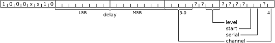
Set Trigger Configuration (C2h, C6h, CAh, CEh)
Configures the selected trigger stage. The opcodes refer to stage 0-3 in the order given above. The following parameters will be set:
- delay
If a match occures, the action of the stage is delayed by the given number of samples. - level
Trigger level at which the stage becomes active. - channel
Channel to be used in serial mode. (0-31 in normal operation; 0-15 when demux flag is set) - serial
When set to 1 the stage operates as serial trigger, otherwise it used as parallel trigger. - start
When set to 1 a match will start the capturing process. The trigger level will rise on match regardless of this flag.
(Command available as of protocol version 1.)
Set Divider (80h)
When x is written, the sampling frequency is set to f = clock / (x + 1)

Set Read & Delay Count (81h)
Read Count is the number of samples (divided by four) to read back from memory and sent to the host computer. Delay Count is the number of samples (divided by four) to capture after the trigger fired. A Read Count bigger than the Delay Count means that data from before the trigger match will be read back. This data will only be valid if the device was running long enough before the trigger matched.

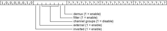
Set Flags (82h)
Sets the following flags:
- demux
Enables the demux input module. (Filter must be off.) - filter
Enables the filter input module. (Demux must be off.) - channel groups
Disable channel group. Disabled groups are excluded from data transmissions. This can be used to speed up transfers. There are four groups, each represented by one bit. Starting with the least significant bit of the channel group field channels are assigned as follows: 0-7, 8-15, 16-23, 24-31 - external
Selects the clock to be used for sampling. If set to 0, the internal clock divided by the configured divider is used, and if set to 1, the external clock will be used.
(filter and demux are only available with internal clock) - inverted
When set to 1, the external clock will be inverted before being used. The inversion causes a delay that may cause problems at very high clock rates. This option only has an effect with external set to 1.
Could you update the protocol specs with the run-length encoding flag and detail the output format? (I could find it in the Java Client\'s sources only)
Hi, investigated data flow on RS232 bus with RS232 monitor program I noticed that in command 81h where data of sample is sent the actual value is slightly different from the label in program. For example if I set in client to use 8k point then in command it is written LSB (FF) MSB (07) which means 2047 x 4 = 8188. Why is that so, why not exactly 8000? If in some situations I want to use 11k point and command I will send manually via LabView interface what value should I sent in 81h command to read 11k memory?
Thanks for advice.
Best regards,
Aivaras
I\'m trying to port this design to a board using an FTDI chip to convert 232 to USB.
Did you considered some particular delay in implementing the JAVA client? Cuase I\'m not able to communicate properly with the client, ID command is working fine but other commands seems to do not work.
Thanks for your help
What is the intent here when sending samples if there is a non-multiple of 8 channels?
For example, I am doing an FPGA project for a class where I am capturing 18 or 36 channels because that is the width of blockrams on more recent Xilinx FPGAs ...
Do I send 4-byte samples with the upper 14 bits zeros, or 3-byte samples with the upper 6 bits zeros?