FPGA basierter Logikanalysator
Das Ergebnis dieses Projekts ist ein Logikanalysator für den Heimbedarf.
Das Projekt umfasst den eigentlichen Analysator in VHDL (für Spartan 3 FPGA) und eine PC Software für den Endnutzer. Als Platine kommt ein leicht zu beschaffendes FPGA-Board zum Einsatz.
Features
- 16 Kanäle bei 200MHz Abtastfrequenz
- 32 Kanäle bis 100MHz Abtastfrequenz
- State-Analyse bis 50MHz über externen Takteingang
- 256KSamples Speicher
- Störungsfilter
- Komplexer serieller und paralleler Trigger mit vier Stufen
- Extern verfügbare Sampling-Clock um Add-Ons anzusteuern (zB. ADCs)
- Kommunikation ber EIA232/RS232 (funktioniert auch mit USB-Adaptern)
- Java Auswertungssoftware (siehe PC Client für Details)
- I2C & SPI Protokollanalyse
Hardware
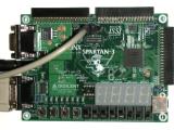
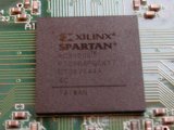
Der Analysator nutzt ein 'Xilinx Spartan 3 Starter Kit (DO-SPAR3-DK)' Experimentierboard von Digilent. Dieses Board ist mit dem Xilinx FPGA XC3S200-4 bestückt, der über 4ns Propagation Delay und 3840 Cells verfügt. Auf dem Board finden sich weiterhin 1MByte 10ns SRAM und eine ausreichende Menge Anschlsse, die als Signaleingänge genutzt werden können.
Ein vergleichbares Board selbst zu fertigen, wäre eine schwierige Aufgabe fr ein Heimprojekt. Der niedrige Preis von USD100 läßt den Aufwand auch nicht lohnenswert erscheinen, da die Bauteile in Einzelstcken kaum billiger zu beschaffen sind. Alles, was noch getan werden muß ist den FPGA zu programmieren. Eine Übersicht ber den VHDL-Code findet sich hier:
Informationen zum verwendeten Übertragungsprotokoll sind auf dieser Seite:
PC Software
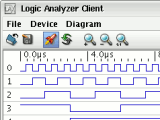
Die Software ist in Java geschrieben, damit sie auf nahezu allen modernen Rechnern mit serieller Schnittstelle genutzt werden kann. Für den Zugriff auf die serielle Schnittstelle wird die RXTX Bibliothek genutzt, die für 34 verschiedene Plattformen - einschließlich Linux, Windows und Solaris - verfügar ist.
Die Software wurde für JRE 1.4.2 entwickelt und sollte natürlich auch mit neueren JREs funktionieren. Mehr hier:
Lizenz
Für die Dateien in den downloadbaren Archiven gilt die GNU GPL.
Downloads
Die Archive enthalten Dateien für PC Software, FPGA und Tester.
Unter History ist eine Liste der Änderungen zwischen den Versionen.
"Official" Version
Logic Analyzer Package v0.8 - Binary (2007-03-03)
Logic Analyzer Package v0.8 - Source (2007-03-03)
User Contributed Versions
These downloads are provided without any testing.
Altera DE2: Experimental Port to Verilog for Altera DE2 Board - Source (2007-05-21)
(Contributed by Kenneth Tsang. Uses external SRAM.)
Altera DE2: Experimental Port to Verilog for Altera DE2 Board - Source (2007-05-21)
(Contributed by Kenneth Tsang. Uses internal M4K SRAM.)
Spartan 3E: Experimental Version for New Spartan 3E Starter Kit - Source (2007-03-08)
(Contributed by Jonas Diemer. Uses internal BRAM with optional RLE.)
Archive
Logic Analyzer Package v0.7 - Source (2006-12-31)
Logic Analyzer Package v0.6 - Source (2006-08-19)
Logic Analyzer Package v0.5 - Source (2006-06-18)
Logic Analyzer Package v0.4 - Source (2006-05-23)
Logic Analyzer Package v0.3 - Source (2006-05-05)
Hello sir
This is Nagarjun here , doing my engineering in National Institute of Engineering ,Mysore. we are been doing implementation of logic analyser using altera de2 board. we have been able to acquire the data from an external digital system and also display it using the signal tap , but our aim is to display the signals using the vga monitor to which input can be fed through the vga out provided in the altera de2 board. its here we are facing problems as we are not able to display 8 channels using the single dac in the altera board, so if u can give us some guide lines or tell us how to go about it will be of great help.
[Edited by Micha: Removed source code as it did take up too much room.]
Seeing your concerns about only having one DAC for the VGA display, you might want to have a look at what a VGA signal looks like for a start. For a very simple solution all you need to do is implement a line counter and draw each signal in its own line. You might want to draw from RAM so all lines will show the exact same time slot.
Apart from this I can't help you as your issue doesn't really have to do with my project.
Micha,
I cannot thank you enough. I can't really afford a logic analyzer right now, but I did have a digilent board in my stash. I built this, and it works great! I had to recompile the source for my xc3s400 board though.
I hope you don't mind me asking a quick question - what exactly do the triggers do? Are they used to start the capture when, say, channel 3 goes high? Or do they have another use?
Again, thanks a ton!
-jeremy
The source has to be recompiled for all but the XC3S200 device, because the configuration image depends on the number of logic cells.
Yes, the sole purpose of the trigger is to start the capture when certain conditions are met.
In the simplest case the capture starts when all channels where the mask field is checked have the specified values. (1 = checked; 0 = unchecked) If the trigger is in serial mode, the bits apply to the last 32 bits sampled on the configured channel.
Multiple stages can be used to configure more complex scenarios where multiple conditions have to be met over time before the capture starts.
Hi,
I just wanted to make quick question about the VHDL code in SRAM block. I ve tried the code but when I simulated it in modelsim the address counter wasnt working. I dont know why. I thought that the simulator cannot guess which one of the two process to run first.
Thanks
You mentioned that you used a digilent board. I searched their website and the only Match I found according to your specifications is Nexys. It seems that this board is deprecated. Does your code work with Nexys-2 ?
Thanks! This is really an amazing piece of software!
@Spyros:
Only one of the processes has an impact on the address counter. There should be no dependencies between the two. Are you sure you applied the proper read/write signals?
@bazzoola:
Check the digilent site for the "The Spartan-3 Starter Board". Its in the list below the Nexys-2.
I would not recomment the Nexys-2 as it uses Dynamic RAM for which there is no support in the analyzer yet. (It is uncertain if there ever will be full support, because DRAM is usually a lot slower than the SRAM.)
Hi, anyone tried the Spartan 3E Starter Kit version with success? The client can't connect to the board. I'm using a RS232 to USB converter, could this be a problem?
How do I use this? Do I just add the sources inside the fpga folder into my project and generate the file?
Im geting error with synthesizing =( Im using the Spartan 3E starter kit
Hi Micha,
What do you think about the SPARTAN 3A Board ? Thats a new development board, which just costs around 40 US$. If an adaption to that board would be possible, it would be perfect.
Any ideas?
cheers,
Daniel
@nagio:
I'm using a RS232 to USB converter myself without any problems. Have you tried lowering the transfer rate?
@Zhane:
Did you adjust the device settings for your board? Did you add the ucf file too? What is the error message you are getting?
@Daniel:
This board has the same problem as all the newer ones: it uses slow (DDR) SDRAM instead of fast SRAM. There is no SDRAM support built into the analyzer, so you would be limited to the FPGA internal BRAM.
Apart from this I cannot tell you if the 3E version (which uses BRAM) will work on a 3A board.
yes, but the result is always the same. I've tested the RS232 connection between the board and the laptop using the examples on xilinx website and they works so I don't think the problem lies in the converter.
Unfortunately I do not have a 3E myself, but it works for others. You might want to try to connect the on-board LEDs to input channels or bits of registers (like trigger mask or speed) to see if the analyzer is running at all.
In the offical analyzer package for the regular starter kit the serial rx & tx are also connected to LEDs. If thats not the case for the 3E by default, you should connect those too to see if there is any activity.
Also make sure you are using the client that comes with the modified package, because the regular client does not support RLE.
Dear Michael Poppitz,
I tried Your logic analyzer with my newly arrived Spartan3E Starter Board,
it works really fine (WebPack 9.2i). Congratulations for your clearly structured sources.
There are just some little problems left:
1. I am using serial port DCE with a USB-Serial Converter (DA-70145- Rev 2.0 from Digitus).
On my desktop PC it installed as a "Motorola Comp Modem" (USB-Serial Controller) and everything works fine.
On my Laptop PC it installed as a "Prolific USB-to-Serial Comm Port" (USB-Serial Controller) and it works fine with Hyperterm
and my FPGA UARTS but not with your Client. Baudrate, Handshale etc is double checked. - Any Suggestion for debugging?
(Device Id returned is 0x0; device not found)
2. Are there any works done for a glitch detector? I think I would like to have one.
3. Do you know if anybody has written a User Manual for your analyzer?
Yours
DI Hermann Dum
HTBL Hollabrunn
Hi,
i have a Digitus (includes Prolific chip) USB-RS232 converter, too. It works fine but not with the original MS drivers. So, how to get it running: goto http://www.ftdichip.com/Resources/Utilities.htm and load the "Microsoft USBView" tool. Check with this tool which plXXXX chip is in your USB-RS232 converter. Then goto http://www.prolific.com.tw/eng/Download-2.asp?ID=17 and load the driver for your chipset and install it. Then the converter should work.
regards,
Frank
any tutorial on how to set the triggers? Ive managed to make it work..but im clueless with how to set the triggers
thanks, my problem was the version of the client software I was using, I've found a precompiled binary for the spartan 3E board and it works
How can I program the spartan 3E board using the logic analyzer code to output at the monitor directly using the VGA port of the board?
PLEASE HELP...
Have you tried using the Digilent Port Communications Utility to communicate directly with the FPGA without needing a serial to USB converter? I have researching the possibility of swapping the RS232 module for a USB module but as I have no knowledge of JAVA I can't modify your code and would thus require that I create entirely new graphing/analyzing software.
I found that the digilentinc product "S3BOARD" works with the logic analyzer. (I recompiled but I'm not sure if this is necessary)
I may have encountered a bug: I selected 200MHz sample rate and only enabled one channel bank. I got my sampled signal interspersed with "0"s. When I sampled at 200MHz and selected two banks, I got the results I expected. Sampling at any other rate than 200MHz did not have this effect.
More on my first experiences with the logic analyzer at http://emergent.unpy.net/01216696167
Thanks a lot...
I will try to do it...
I am very interested in it...
I will try to make the hardware of it first...
So that I will be motivated to do it...
I synthesized the program then it is ok...
I implemented the program then it went bad, itleaves an error...
what seems to be wrong in the program?
Can someone in here help me?
Just want to know where is the main cause of it
Very nice project. I was looking for an affordable logic analyzer for my emulation-related stuff, and I was thinking about using my Starter Board for this purpose. That's exactly what you did, and in a very nice way. Congratulations for the project itself, and the extensive amount of documentation you provided.
Regards,
Greg
I love your work. I have the hardware and software all functioning. I have found that the zoom function does not work very well. When zooming in (and out), the currently viewed part of the waveform is moved out of the visible window. It would seem that the window position needs to be manually updated to compensate for the zoom factor.
I am new to Java and relatively new to OOP, but I was trying to work on the code using Eclipse. I can not seem to find a way to interact with a viewport object to change the visible region. I would love to do a little work on this and then give you the final result. Do you have any pointers for me? E.G. Would making the Diagram object extend JScrollPane rather than JContainer be useful? I have tried all sorts of xxx.getParent() to get a useful viewport without any luck. Since I am very new to Java, I have run out of ideas.
Hi,
did you use the latest sources from http://sourceforge.net/projects/jlac/ ? It has cursors with a "goto" function included. This could be used as a base for setting the viewport position after zooming.
Br,
Frank
Hi,
First off Micha, thanks so much for this wonderful tool! I'm looking forward to working with, and extending it.
Secondly for those out there who see good "bang for your buck" on the NEXSYS2 board, I was able to get the software to work with 20khz and 100khz signals with the NEXSYS2 board. I used the code from "Spartan 3E: Experimental Version for New Spartan 3E Starter Kit" modifying only the .ucf for the fpga pin assignments. I do not have a signal generator that is much faster than that at this time, so I cannot comment on the performance at higher speeds, but I'm assuming it should be okay.
The RLE included in the above code gives me garbage - but I'm not worried about that feature right now.
Thanks for the impressively well written and understandable RTL.
I was wondering, have you considered implementing the Sump Analyzer on larger FPGAs and use it as a means to monitor internal signals much like Altera's Signal Tap II Logic Analyzer? The logic is probably small enough to fit along side an existing design in a Altera DE1/DE2.
I have written a user guide for the current Logic Analyzer client that you may find useful - see oakmicros.com/content/downloads/View-document/Logic-Analyzer-User-Guide.html
I also sell a logic level interface board called the omla32 that allows up to 5V for the 32 inputs and optional external clock. See oakmicros.com/content/omla32-Logic-Analyzer-Interface-Card.html
I just received my Digilent starter kit and had this Logic Analyzer work
in just a few minutes! I am really impressed to say the least ;0).
I plan to change the onboard SRAMs with two 2Mx 8 IS64WV20488BLL
http://www.issi.com/pdf/61-64WV20488.pdf
I do not really need 32 channels and I think a 16 channels with a 2M buffer
is more useful after I do some tinkering with the VHDL model.
Great Work!
Some comments for Linus.
I think you will find that the extra address line you need is not connected to the FPGA and you will need to solder in something yourself.
Also there is a version of the FPGA code that does a run length encoding (RLE) of the data to reduce its size in memory. This may be suitable for your needs. The Java client for RLE needs a bit more work and is available from http://sourceforge.net/projects/jlac
I would think that I could sample 5v signals by using 3.3v Zeners instead of building the add-on board? I.E. Each input would have a resistor and then a zener which would give a max of 3.3v...
@ Mike Perks
Thanks for the heads up Mike. ;O)
I plan to remove both of the stock SRAMS and replace it
with just 1 BIG SRAM. This will give me enough I/Os for
the wider address lines.
I did not check the original VHDL code yet, I actually used
the ones on your site hehehe.
Btw, I will be ordering your add-on board ;O)
B.R.
I am searching for a cheap compatible board with SRAM(!).
Whats about the Zefant LC3E Board?
It contains a XC3S??? (??? = 250.000 macro cells), with 4MB SRAM and 32 MB Flash.
In germany it costs less than 100EUR.
The
http://shop.trenz-electronic.de/catalog/productinfo.php?productsid=172
Christian
Sorry, it is a failure in the data:
only 4MBit SRAM = 512kByte; and 32MBit Flash = 4MByte (!)
Christian
Hi,
I just received my digilent board and intended to use my arm-usb-tiny from Olimex to program. But the xilinx webpack does not seem to support this jtag interface. I did manage to have openocd report a two-device chain, so I presume the hardware is connected correctly. But that's where I ended.
Can somebody please help me on configuring openocd (or an other way) to program the board?
Tnx,
Joep
Hi!
I m a student of B.tech 3rd year and we have been asked do a projejt on VHDL and i m not getting what sort of project can be done in this.
So, I shall be highly obliged to u if u can suggest me some project.
Thank you.
The "omla32" logic level interface board I announced here just over a month ago has been very popular. I am happy to report that they are in stock again. See http://oakmicros.com/content/omla32-Logic-Analyzer-Interface-Card.html
I also have written a user guide for the current Logic Analyzer client that you may find useful - see http://oakmicros.com/content/downloads/View-document/Logic-Analyzer-User-Guide.html
hi
i am 3rd yr student. can some one tell the concept of how sampling is done in this project.
hi. i am a 3rd yr student. pl help to understand the concept of sampling done in this project
I tested this project using Altera Cyclone chip (Nios Dev board). The only problematic place is serial link. As I don't have RS232 on my computer I was using FTDI chip (ft232). I've tested several transmission speeds but only low speed ones are usable. At high speed only small part of data are transmited then system crashes. I don't this it is hardware problem as I transfered data from other projects using save chip at very high speed. I think it is problem in java software.
I wrote small article about it in my blog (sorry, still no english translation).
http://www.vabolis.lt/2008/03/26/loginis-analizatorius/
Hi,
great work ! I tested the file for a Spartan 3E demo board, without any problem.
The above problem with serial port could be the XON/XOFF.
I had to add a synchronizer for the rx pin on the Nexys2 board. Otherwise I observed metastability issues.
Dear Sir, Could you please give me the idea of the overview of this project...i am a bit confused.I want to know what is the use of FPGA here?..can the java client like be made in Matlab..if so how?Could you please send me the details of the project?i will be very glad.
Thank you.
my email address:\"theneupane@hotmail.com\"
I managed to get it running on a Spartan 3 with xc3s1000, omla interface and ISE 11.2, runs at 115K just fine.
cheers!
Sir,Can I get the documentation of the project.I need it urgent.I will be grateful to you for this approval.
email:theneupane@hotmail.com
Dear sir,could you please send me the documentation of the project...i will be very grateful to you for this?
email:\"theneupane@hotmail.com
Hi, I have done a project on the same platform xc3s400 for image edge detection. We did it using a college FPGA kit, and I am wondering how much it would cost to setup a development environment.
The \"Sump\" Logic Analyzer is also running on a completely Open Source FPGA board called \"Butterfly Light\". Eagle schematic and board files are available for download as well as a precompiled version of the very latest Java Client which was checked out from CVS. For those who are not interested in building their own boards there are assembled boards available for purchase.
Screencasts on usage of the Logic Analyzer are available and more are on the way, so keep checking back.
Project page is http://www.gadgetfactory.net/gf/project/lax/.
Just a quick note - the Spartan 3E version of the analyzer works great on the cheap avnet spartan 3A board (SRAM-less). The only adjustments required are (obviously) the pinouts and clock setting.
Andrzej,
Could you please post the VHDL source for the 3A? or send it to me at jiggly67@yahoo.com
Thx.
Hi Andrzej,
could you please post the VHDL source for the Avnet Spartan 3A board or send it to me: bauerp@hotmail.com
Cheers!
Are there any limitation in using the Avnet 3a board
Please also send the the VHDL source to me
rfhn@hotmail.com
Thanks
There are many boards suggested as a base for the Logic Analyzer. Since I know very little of these products can someone help me by posting the #samples, Sample Rate, and if appropriate the # of channels each of the following support
Gadget:butterfy
Spartan 3
Spartan 3A (SRAM-less).
Spartan 3E 1Mb?
NEXSYS2
Thanks
Hallo,
Ich will mir Deinen LA mal bauen.
Das Spartan 3 Starter Kit gibt es in 2 Varianten.
Eins mit 200k und eins mit 1000k Gates.
Welches brauche ich?
Ich habe noch nix in FPGA gemacht...
Danke
Gruss Andi
Such a really great job this logic analyzer.
Michael I am studing an expertise in embedded system. The project I will perform is a basic logic analyzer. I would like to see if you could give a guidance. In this way, which information do you recommend me to read about first and so on. I\'ll appreciate your help.
Thank you in advance.
P.D. My email: salazarortega@hotmail.com
@everyone requesting the Spartan 3A version:
Sorry for the obviously late response, I haven\'t been checking this page recently. I\'ve put a tarball here: http://kuku.eu.org/s3ala/s3a-la.tar.bz2
Thanks Andrzej, it works great with the AvNet S3A board. I think I\'ll try to re-spin it to reach 100MHz. It looks like
50MHz is the max sampling rate currently (78MHz in the Xilinx timing summary).
@Micha: DDR SDRAM is not slow, you just need to write a proper controller. It\'s a lot more complex than SRAM/BRAM though.
See http://www.milkymist.org/doc/hpdmc.pdf
The logic analyzer and it\'s open protocol are very interesting, however, Java ruins the thing as far as I\'m concerned. (slow, clunky, unreliable, huge, dependant on an ever changing runtime executable, etc ...) A standalone C (or any compilable language you want) program would be a vastly superior alternative.
Java is compilable into native machine code by GCJ (in GCC), at least for some platforms.
Hello,
We are working on a low cost ($30-40) Open Source implementation of the Sump Logic Analyzer based on the Spartan 3E. All help and input is greatly appreciated, come take a look and help us get this project completed.
Please join us at http://www.gadgetfactory.net/gf/project/butterflylogic/
Thank you,
Jack.
Hi,
Could sampling speed be much higher? For example using four 100MHz clocks each phase shifted with +90, so we have clock1 PS 0, clock2 PS90, clock2 PS180, clock2 PS270 and we have 4 memories to write data from each clock and 4 different process which write data to memory?Thus we can get 4 samples per one period?
boki
Hello boki,
You could imagine to use 4 phase shifted 90 degreed only if you want to sample signals in the FPGA. If you want to use PIO (IO port, sampling external signals) you have to use dual rate flip-flip architechture only.
Regards,
Laurent
http://www.amontec.com
Amontec JTAGkey-2 High-Speed Generic USB JTAG adapter.
For anyone else trying to compile for an S3Board with ISE 11.1, change d9 to n8 in la.ucf to get rid of the \"This will not allow the use of the fast path between the IO and the Clock buffer\" error. From what I can tell from the datasheets, this is the only global clock site able to be connected to a clock mux with t9 which isn\'t used for something else on the board.
Hi Fishfish,
What version are you using. The v0.8 synchronize exClock with xtalClock, so there are no need of GCLK on exClock.
Laurent
http://www.amontec.com
Hi, tried to implement the design on an S3Board with 1000k gates with ISE10.1 and ISE11.4. With the exception of the \"CLOCKDEDICATEDROUTE = FALSE\" for the exClock I have not changed anything. Unfortunately nothing works - I cann see the signals on the 7Seg leds but when I press capture the signals went off and I only get zeros as a result.... Any Ideas?
I've used the LA for awhile and was impressed with the open source version. So I decided to plug both here http://www.drdobbs.com/blog/archives/2010/04/homebrew_gear_p.html
I also added the code for a trigger output (about 600uS pulse when the device triggers). See the above link for more.
Thanks a lot!
Own a Spartan for programming in past days, with your project I can now use it as LA, too - making it useful again and taking really advantage of its speed. Perfect application.
Will replace old osci in many cases now and helped me out with a tricky problem concerning my notebook (the reason I actually looked for an LA) were I needed >20 channels. The 100 MHz sampling is great, memory and trigger impressive.
And everything for free :-)
Thanks a lot again!
Hello everyone, I am having problems extracting the files from the tarball. I have tried a couple of different extractors, but I keep getting an error saying that the files are corrupted. Does anyone know a free extractor that works? I am running Windows XP. Thanks!
try 7zip under windows
Thanks a million nuess0r! You are awesome!
As an embedded software engineer, I use very complex triggers for debugging. I\'m interested in implementing more complex triggers on this platform.
I used to use an Arium 4400 and loved three of its features:
Enable/disable of storage: Each trigger level would let you select whether to store signals while the state machine was on that level. So you could store several sections/times of interest prior to the trigger.
Full state machine: From each trigger level, you could go to any other level, on any of several conditions.
Event-based \"transition\" mode: You could leave it running for minutes at a time, watching a seldom-used serial channel, and it would store the transitions without filling up memory with no-ops.
I think I know, at a high level, how to implement all these things, but I\'d like to work with someone who has more experience with FPGA\'s. I\'ll be developing for the OpenBench Logic Sniffer board.
http://www.seeedstudio.com/depot/preorder-open-workbench-logic-sniffer-p-612.html?cPath=75
Anyone interested in helping me develop any of these features?
What\'s the best free software to use for editing/compiling the FPGA package?
Email cphoenix at my gmail account, or leave a message here.
Chris
Without too much trouble, I got the client software to work on OS X 10.6. The trick was to get the most-recent version of rxtx from http://rxtx.qbang.org/pub/rxtx/rxtx-2.2pre2-bins.zip.
The client already includes RXTXComm.jar, so all you need to do is put libSerial.jnilib in the same directory as analyzer.jar (and the shell script used to start the app). Just make sure you choose the correct analyzer port (my Radio Shack USB-to-Serial dongle shows up as /dev/tty.PL2303-serialnumber).
I know very little about Java but I suppose I should be able to hack the app to support more channels and more buffer depth, as I want to extend the thing to use the DDR SDRAM on a S3-1600 kit I have.
Call me a liar ... the above all worked fine on my iMac but of course the client fails with a java.lang.NoClassDefFoundError: gnu/io/CommPortIdentifier error on my MacBook Pro. Grrrrrrr.
I am trying to compile the java client in Windows XP
I get the error
cannot find symbol: class MainWindow
Can anybody give me some clue ?
-Viresh
hi to all
Anyone knows if Basys2 FPGA Board is usefull?
Thanks in advance.
Andy Peters: Did you have any luck with DDR SDRAM?
Thanks
Hi to all.
Will also very appreciate any qualified response to dan\'s question, as this hardware is much cheaper (Academic price $59, student price $49) and offers Atmel AT90USB2 USB controller as bonus. See:
http://www.digilentinc.com/Products/Detail.cfm?NavPath=2,400,790&Prod=BASYS2
Cher monsieur,
je suis un tudiant et je veux approfondir mes connaissances dans ce domaine, pourriez-vous s'il vous plat de m'envoyer la documentation ou les tapes dtaills de la conception du projet?
je vous remercie l'avance!
Sir,
Can I get the documentation of the project.I need it urgent.I will be grateful to you for this approval.
email:rakotoariren@yahoo.fr
I was wondering if there's an easy way to get a .csv or some similar format out from the software. My application has a number of binary channels and I'd like to just get the value and timestamp associated with each of those out to something I can process.
Thanks!
Gerry
Hi,
I had a project in Altera DE2 that works with SRAM. It was written in Verilog; now I have to move on to Genesys Virtex 5, but as you know, there is no SRAM in this board, so I need to use either StartaFlash or DDR2.
Would you please help me to find out how I can use StartaFlash or DDR2? It would be great if you provide me the verilog code or the way to find the code.
my email is masoud.bahramisharif@du.edu .
Best,
Masoud
01/01/2012
Hi,
I have a Spartan3A board(Xcs3s700a-4fg484) which is not compartable with the Sump as it stands,mainly due to the ddr2 memory
In order to get it working I had to change most of Michal Poppitz code to suit.
I would like to express my thanks to Michael Poppitz,without his original code i would'nt have stood a chance.
The specs are the same as the Sump except for 16 channels.
I have tested it as well as i could with the limited means at my disposal and it seems to function as it should; But its difficult to be %100 sure without feedback and comparison.
So if anyone is intrested I would be more thn happy to share it with them
Thanks
cmgpalton@btinternet.com
Conrad
I would like very much to see NRZ and NRZI analyze under tools!
In all a very useful analyzer, in speed vs cost.
It seems like you may be the guy to answer a question I've been asking myself.
I deal with a lot of 74 logic and could really use a nice universal way to test these ICs in circuit.
I know there are a couple of tools out there to do this but frankly, they were made in the 70s and are not exactly a catch all solution.
How hard would it be to build a small device with a 20 pin IC clip to quickly test if a logic IC was bad? The old HP testers use physical ICs to compare the output to the IC under test, but surely this could be accomplished in an FPGA by simulating the logic?
I understand in some of the more complex devices there may be an error margin but are vhdl sources out there of most 74 devices or is this something that would need to be done per device?
I guess the real question is, has someone already done this that you know of? I find VHDL far too complex myself or I'd have a crack at it.
Anyway, great project!
Micha,
Great job -- thanks a bunch. I am a newbie with FPGA development, and this seems like a good project to learn. The VHDL appears well written, well modularized and relatively easy to understand.
I tried to build the FPGA for the Digilent eval board using ISE 13.4, but it returned an error about the xtalClock not being placed optimally with the DCM component. I used the Xilinx implied work-around in la.ucf:
NET "xtalClock" CLOCKDEDICATEDROUTE = TRUE;
and it builds without errors (although lots of warnings). The problem is that it does not work reliably -- it hangs most of the time (the client cannot upload from it or claims it is not connected). I used the bit file on the site generated with ISE 8.2 and everything works, so I know the board, COM port and the client work.
Has anyone done a reliable build using the ISE 13 tools? I'm sure the issue is in the constraints file, but being a newbie, I don't yet know how to fix it.
Thanks again for this wonderful project.
I have the same exact issue than Manuel (Wed, 27 Jan 2010) and lancej (Sun, 29 Apr 2012) when building 0.8 with Webpack 14.4.
I'm following Xilinx recommendation to set the following UCF's parameters:
NET "xtalClock" CLOCKDEDICATEDROUTE = FALSE;
PIN "Instclockman/DCMbaseClock.CLKIN" CLOCKDEDICATEDROUTE = FALSE;
Has anyone been able to generate .bit file that works using ISE >10.1?
Thanks!
I was unable to get the spartan 3e version working as is with my usb->rs232 cable. I believe it was due to some latence issues. This one uses the Asix chipset. If it's useful to anyone I found that I could fix the "device not found" error by extending the count variable from 10 to 20 in the receiver.vhd READY state as follows
when READY =>
ncounter <= counter + 1;
nbitcount <= 0;
nbytecount <= 0;
nopcode <= opcode;
ndataBuf <= dataBuf;
if counter = 20 then
nstate <= INIT;
else
nstate <= state;
end if;
after this transfers work every time. Also I could not use the RLE option. If I figure out why I will post it here.
More info. I bought a new FTDI based USB to RS232 and found that setting the receive/trasmit time out in the driver settings to 1000ms (under device manager/ports/ftdi device/settings) it works flawlessly at 115,200 baud (and 19,200 as well, just too slow :) ). The default settings will not work, and you get stalled transfers or "device not found". I think the real way to go with these things is onboard RS232 ports, but my lab computer is a laptop so I adventure forth with usb. I plan on looking at the verilog version next, as the verilog language interests me more.
This looks like a great project.
You mention development boards as an option to run the FPGA VHDL code. An interesting kickstarter may be a good option in the future.
See:
http://www.kickstarter.com/projects/1575992013/logi-fpga-development-board-for-raspberry-pi-beagl/comments
With that said, do you have any thoughts about using a raspberrypi or beagle bone black, BBB, to connect to the FPGA board? Not sure if that is clear. Mainly, do you feel the SUMP VHDL code and the Java client could run on a PI/BBB with the kickstarter board?
Thanks,
Jay.
¤¤¤¤s30Äg¤¤¤Ag¤r¤¤¤¤¤¤¤A¤¤¤¤¤¤¤¤µr¤¤ß¤¤¤¤¤A¤ßm¤¤¤¤¤¤¤¤¤¤¤¤¤¤¤¤¤¤¤¤¤¤¤r¤¤µ¤Ö¤¤äĤ¤¤¤¤¤¤¤¤Ö¤¤¤¤¤¤¤¤¤ä¤¤¤¤¤¤¤Üܤ¤¤¤¤¤ß~¤¤¤¤ÜÜÖ¤ö¤Ö¤¤¤¤Ö¤z¤¤¤¤¤¤¤Ö¤¤¤¤¤¤¤¤¤¤¤¤¤¤¤¤¤¤ö¤¤¤¤¤¤¤¤¤¤¤ö¤¤¤¤¤¤¤¤¤¤¤¤¤70032C¤¤¤¤¤ä¤Ä¤¤¤¤¤¤vS¤¤¤¤ä¤äµ¤¤¤¤¤
[url=http://www.g-show.com]7[/url]
<a href="http://www.g-show.com" title="7">7</a>
Being fairly new to the FPGA world it's a lot to take in. I've loaded this project into ISE and have been playing around with it...well, basically looking at it. I guess I have two questions that I would like to ask:
1) What resources would you point a beginner to for FPGA/VHDL coding?
2) How difficult would it be to port this project to the Numato Lab Elbert V2? It's running a Spartan XC3S50A which is a little smaller than XC3S200 FPGA. It would probably require removing a few I/O as when I check the resources I have 108 IO available but the project takes 118.
Again...fascinating project. Great job.
-Joe
Amazing!
And the next thought is that You made it for free so long before Saleae, but hey made a million dollar business from the idea.
Guess I'm a moron too. Where's the link to the Logic Sniffer?
Where do I find the software to install on windows?
This page is so confusing! Where is the beef?
I have a board I bought back in 2010 and haven't used it since. Now I can't install a client to run on my PC! What is going on?